THIS PAGE APPLIES TO THE LnHUA and LnHUAN ONLY
The LnHG2 and LnHG2-2 WILL FIT ALL EVINRUDE G2 MOTORS
|
Will It Fit My Motor?
Don't see a picture of your motor anywhere?
The Lock-n-Haul® works the same way on all motors. Send us pictures of your motor like the ones below, and we'll help you figure it out.
|
IMPORTANT
The Lock-n-Haul®fits all brands and most models and sizes of outboard motors, provided that they have the three key design features generally described on this page.
Your motor might not look like the examples below, but the way the device fits up the same way.
The Lock-n-Haul®employs a patented 4-point inline load design, that connects two of four points with the lower motor mount flange bolts, located on the lower unit just above the cavitation plate at the bottom of the steering pin, and two points connect to the transom motor mount bolted to the boats transom.
Outboard motor manufacturers have many different designs, even in same year and same size and make, so the best policy is to check your particular motor and verify that it has the features described below.
|
Three features are necessary to install the Lock-n-Haul® on your outboard motor.
1) Power outboard motor tilt system
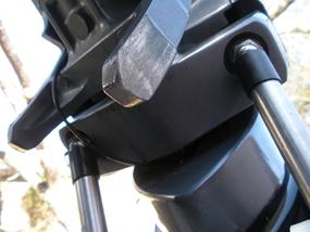
2) Accessible (lower motor mount) steering pivot rod flange bolt heads
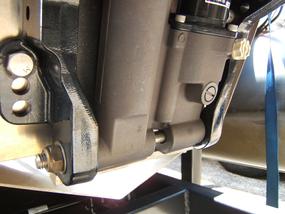
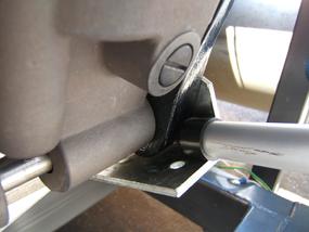
3) Transom motor mount indents/concaves/cradle
*** Long shaft (offshore) motors with 25"-30"shafts ***
See picture at bottom of this page and compare to your motor.
|
|

UNIVERSAL INSTALLATION MANUAL |
LnHG2 FOR EVINRUDE G2 MOTOR INSTALLATION |
| Yamaha, Honda, Suzuki example, necessary installation features |
1) Power outboard motor tilt
|
2) Accessible lower motor mount flange bolt heads
|
3) Transom motor mount indents/concaves
|
 |
| Click image for more detail. |
|
|
|
 |
| Click image for more detail. |
|
|
| Mercury example, necessary installation features |
1) Power outboard motor tilt
|
2) Accessible flange bolt heads
|
3) Transom motor mount indents/concaves
|
 |
| Click image for more detail. |
|
|
 |
| Click image for more detail. |
|
|
 |
| Click image for more detail. |
|
|
| Evinrude example, necessary installation features |
1) Power outboard motor tilt
|
2) Accessible flange bolt heads
|
3) Transom motor mount indents/concaves
|
 |
| Click image for more detail. |
|
|
 |
| Click image for more detail. |
|
|
 |
| Click image for more detail. |
|
|
| Lock-n-Haul not responsible for any loss due to modification |
| Bracket solution for motors without indents/concaves |
Transom motor mount without indents/concaves
|
Simple 'U' or 'L' bracket bolted to motor
|
Transom motor mount and bracket form mounting point
|
 |
| Click image for more detail. |
|
|
 |
| Click image for more detail. |
|
|
 |
| Click image for more detail. |
|
|
| Cradle solution for motors without transom mount indents/concaves |
Transom motor mount without indents/concaves
|
Pin through vertical casting holes
|
Back of transom mount and pin form cradle mount
|
 |
| Click image for more detail. |
|
|
 |
| Click image for more detail. |
|
|
 |
| Click image for more detail. |
|
|
| Plastic cowling covering flange bolt heads solution |
Cut 1" holes in plastic cowling to access bolt heads
|
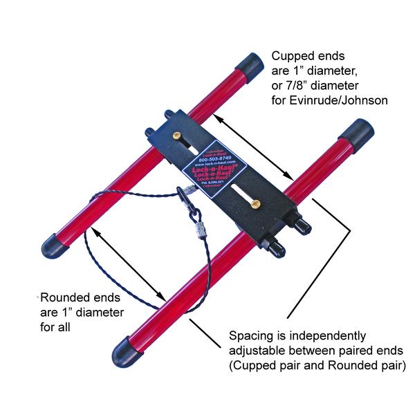
Cupped ends of Lock-n-Haul can access bolt heads
|
Lock-n-Haul sucessfully installed on plastic cowling models
|
 |
| Click image for more detail. |
|
|
 |
| Click image for more detail. |
|
|
 |
| Click image for more detail. |
|
|
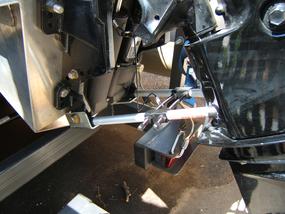
| The Lock-n-Haul on a long shaft motor |
The Lock-n-Haul® is 13" long. The ends are 1" (7/8" for Evinrude/Johnson) diameter and the tubes are 3/4" diameter. Tilt your motor until you have 13" between the lower motor mount flange bolt heads, and the indents/concaves/brackets on the transom mounting bracket. If you can put a 3/4" diameter tube between them then it will work on your motor.
You can also use the picture above as a quick reference. Basically the flange bolt heads and the motor mount features need to line up when the motor is vertical.
|
|